Neptronic’s new TUUB series of wall-mount universal controllers offer the perfect solution for varied application control. In a heat pump application, this series allows great flexibility of control of temperature, humidity, CO2, volatile organic compounds (VOC), and occupancy. For integration projects, BACnet and Modbus remain as the main communication protocols.
In this article, you will learn how to use the TUUB to control your heat pump.
Standard TUUB with Heat Pump Wiring Diagram
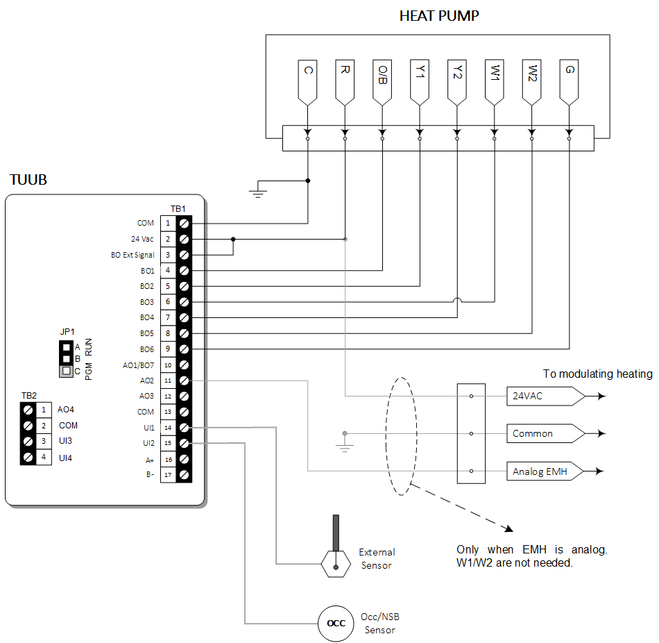
By configuring the Heat Pump option in the TUUB, terminals BO1 to BO6 are set to the following default settings:
| Reversing Valve |
BO1 (#4) |
Fan (Speed 3) |
BO4 (#7) |
| Compressor (Y1) |
BO2 (#5) |
Fan (Speed 2) |
BO5 (#8) |
| Heat (W1) |
BO3 (#6) |
Fan (Speed 1) |
BO6 (#9) |
When a terminal is active, it will output 24VAC, which is the same as the controller’s power supply. All output voltages are referred to the common terminal on the controller.
Upon activation of the Heat Pump mode, some parameters are configured by default;
others may require adjustments to fit the application. Refer to the
TUUB Specification
and Installation Instructions
for detailed instructions. Here is a summary of the configuration possibilities:
Reversing Valve. This is in cooling mode by default. For heating mode, change
configuration in step 13 from ‘o’ to ‘b’ or set the value of the BACnet object BV.96 to 1. Reversing valve is available in terminal BO1 (#4).
Compressor (or First Stage Compressor). It is available in terminal BO2 (#5).
Activation/Deactivation percentages are configurable in steps 47 and 48 or using BACnet objects AV.115 and AV.116.
Heat W1. Also known as EMH (Emergency Heat), this acts as a supplemental heating source.
It is disabled by default. Enable it in configuration menu at step 14 or using BACnet object BV.98. There are two possible operation modes:
- Manual: Press the button to scroll through all the options and select EMH.
BO3 (EMH) will be activated and BO2 (compressor Y1) will go off. BO3 will follow the open/close percentages of Y1 (BO2).
- Auto: Enable EMH Auto Mode in step 15 or via BACnet object BV.97. Once enabled,
it will make the EMH act as an automatic second heating stage (compressor Y1 will remain as the first stage) and will follow the open/close
percentages configured for BO3 in steps 59-60.
Fan.Go to step 38 or BACnet object MSV.25 to change the number of fan speed contacts. Fan at 1 speed will enable the configuration of two extra outputs:
- Second Compressor Y2 through terminal BO4 (#7)
- Second stage EMH through terminal BO5 (#8)
Y2 Output.This is the second compressor stage and is available through terminal BO4 (#7). It comes disabled by default. Enable it in step 45 or using BACnet object BV.99. Y2 is available only if fan speed is set to 1 or 2.
- In the EMH Manual mode, Y2 will go off together with Y1.
- In the EMH Auto mode, Y2 will activate according to the open/close percentage defined in steps 65 and 66.
Heat W2.This is the second stage EMH. It is available through terminal BO5 (#8) and will activate according to the configuration of the open/close percentage defined in steps 71 and 72. This output is available only when the fan speed is set to 1.